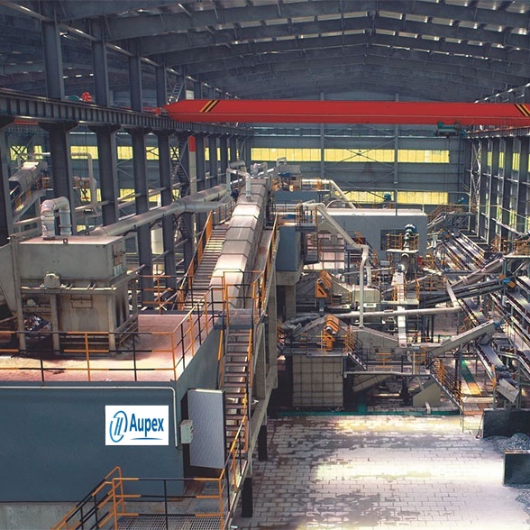
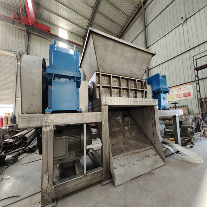
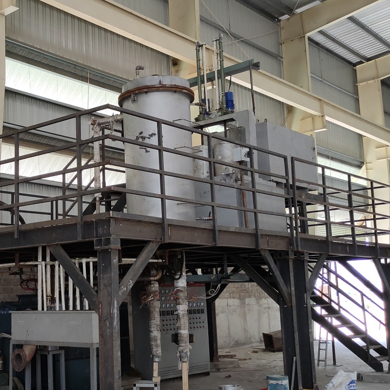
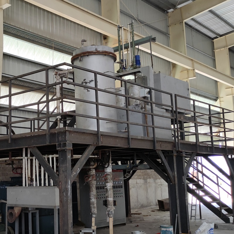
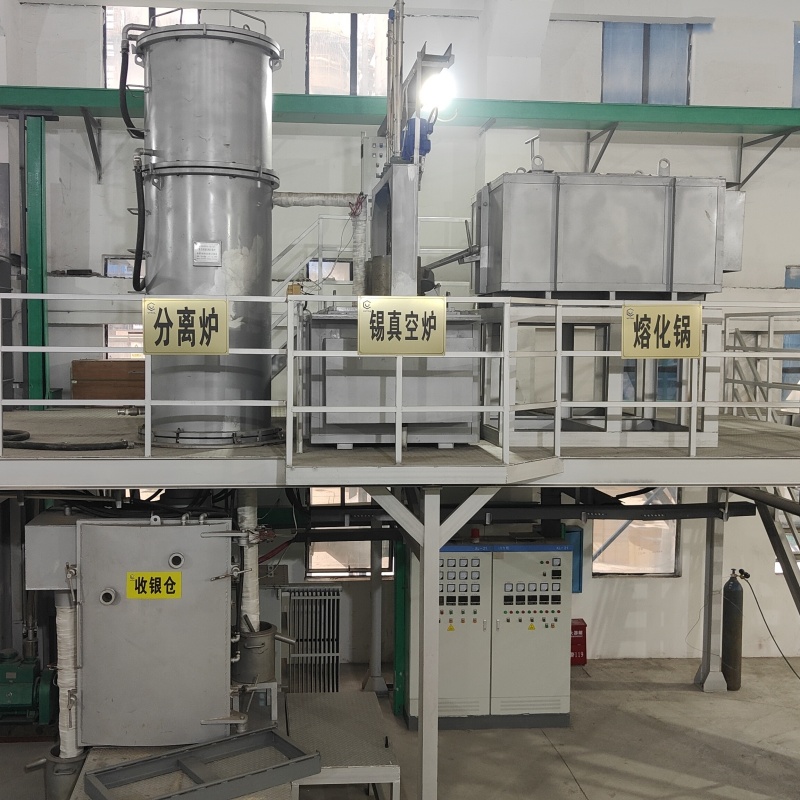
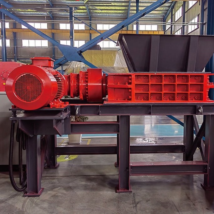
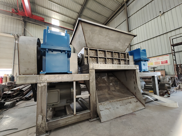
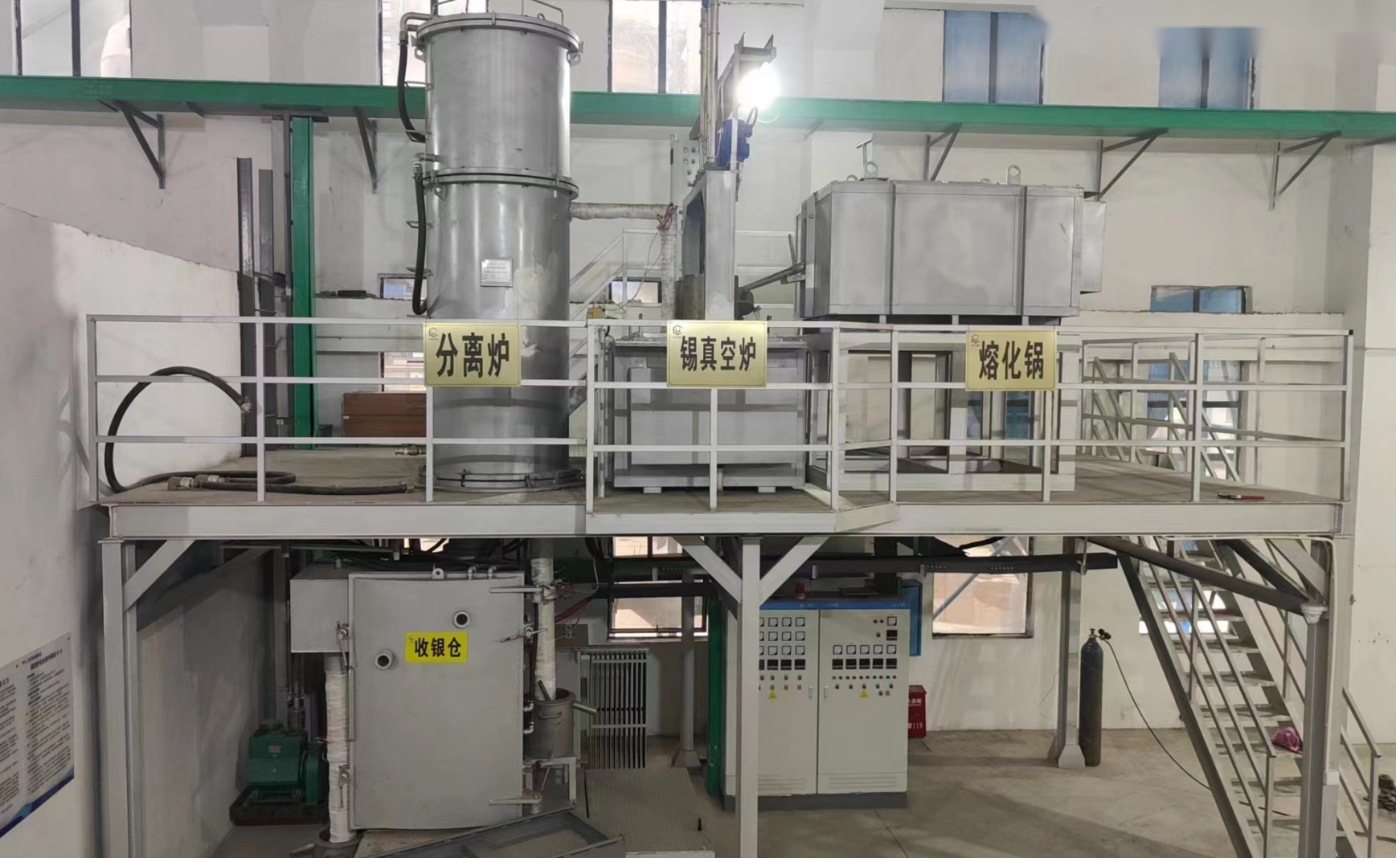
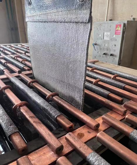
Aupex Tech PTY.LTD. provides a full set of engineering equipment for lead electrolysis smelting, lead electrolysis engineering design and construction, and lead electrolysis engineering process improvement consulting services.

The complete sets of engineering equipment for lead electrolysis and smelting provided by the company include automated production lines for lead anode plates, automated production lines for lead cathode plates, automated production lines for electric lead and lead alloy ingots, automated production lines for lead anode mud treatment, complete sets of lead electrolysis rectification equipment, intelligent complete sets of lead electrolysis process centralized control equipment, and copper busbars for electrolysis engineering.
Lead anode plate automatic production line
Lead anode disc casting unit


Lead cathode plate automatic production line

Automatic production line for electric lead and lead alloy ingots

Lead anode plate residual electrode flexible washing unit
The flexible washing unit for residual lead anode plates can be designed and manufactured according to the requirements of different specifications and sizes of plates. The flexible washing process is to rotate the flexible washing roller to drive the washing sheet to beat the lead mud. The beating force can be changed according to the speed of the washing roller to adapt to various lead muds. The washing sheet has a moderate beating force to beat and scrape the anode mud and wash the anode mud off the anode plate. Due to the different properties of the anode mud and the lead plate, the washing sheet will retreat when it acts on the lead plate, so as not to damage the lead plate. The equipment has an adjustable running speed and adopts double-station flexible washing, with a production capacity of 300 pieces/hour.
Technical parameters
Production capacity: 200-300 pieces/hour;
Installed capacity: 20KW;
Flexible washing method: the plate is lifted and lowered, the washing roller rotates, and two pieces are washed at a time.
Plate specifications: customized (length x width x thickness);
Step distance: 390mm;
Air supply pressure: 0.6MPa (provided by the user);
Machine weight: about 20T;
Dimensions: length x width x height 20000 x 3300 x 3200 (changed according to the size of the anode plate and the user's requirements for the length of the anode plate conveyor)
Working noise: less than 85dB(A).
Equipment technical description
Equipment composition
This equipment is mainly composed of seven parts: chain anode plate conveyor, plate pusher, plate lifter, flexible washing device, anode plate arrangement and output device, air control system, and PLC automatic control system.


Lead electrolysis rectification equipment
Lead electrolysis rectifier
Silicon controlled rectifier power supply
The thyristor rectifier power supply converts the AC power input from the power grid into DC power output. The main circuit of the thyristor rectifier adopts a 12-pulse bridge rectifier circuit. The single bridge arm is composed of a thyristor and a fuse in series. The fuse is used for overload or short-circuit protection. When a short circuit occurs, the fuse will blow to prevent the fault from expanding. Each thyristor is connected in parallel with a resistance-capacitance absorption circuit to absorb the peak voltage during commutation to ensure the safe and reliable operation of the thyristor. The controller monitors the thyristor temperature and fuse status in the rectifier cabinet in real time. When the fuse blows or overheats, the location of the faulty device can be quickly located through the touch screen display. PLC, as the central controller in the control cabinet, completes the logic control of the rectifier, fault protection processing, touch screen communication and monitoring of the data interaction of the DCS system; the thyristor trigger control system equipped with the system completes the sampling, closed-loop control, phase locking and trigger pulse calculation of parameters such as input and output current and voltage. It has protection functions such as overvoltage, overcurrent, undervoltage, short circuit, overheating, phase loss, and overtemperature.
Lead electrolysis rectifier system includes high voltage cabinet, on-load voltage regulating rectifier transformer, rectifier cabinet, rectifier control cabinet, pure water cooler, high current DC sensor, etc.
The circuit principle block diagram is shown below

Main technical parameters of rectifier
Basic technical conditions
1. Rated output DC current: Idn=13000A (load input end), current range: 1000A~13000A
2. Rated output DC voltage: Udn=266V (load input end), voltage range: 60V~280V
3. Rectification wiring method: 2 three-phase full-controlled bridges in parallel
4. Voltage regulation method: primary on-load voltage regulation + secondary thyristor voltage
regulation
5. Cooling method: transformer forced oil cooling, rectifier cabinet pure water cooling
6. Inlet and outlet method: transformer top outlet. Rectifier cabinet top inlet and bottom outlet
Production workshop

Installation site

Silicon controlled rectifier products
Rectifier transformer

High frequency switch rectifier cabinet for electrolysis
IGBT rectifier cabinet for electrolysis
HHF16000A80V high-frequency switch rectifier power cabinet adopts a distributed control power system, with 32 power modules connected in parallel to achieve the output of 16000A80V rated current and voltage.
1. The main circuit of the single power module adopts advanced full-range soft switching technology, with high reliability, low loss, and working efficiency of more than 90%;
2. The single module adopts small and medium power (500A80V), which makes the system stability and flexibility extremely high.
3. It has automatic protection alarm functions such as overvoltage, overcurrent, overtemperature, and phase loss, as well as soft start function.
The whole machine is made with a full range of anti-corrosion technology, which enhances the product's anti-corrosion ability and prolongs its service life.
HHF16000A80V Technical parameters of the power supply system
4. Control motherboard: The control motherboard adopts the latest fully digital boxed modular
motherboard, which is maintenance-free.
5. Control system: Conventional control has constant current and constant voltage control
systems. Under the conditions of 5~100% rated output current and 10~100% rated output voltage, the automatic current and voltage control device ensures that the DC current is constant at ±1.0%. This equipment adds a constant process parameter working control mode. There are process parameter settings (-2.00~2.00V) and feedback signal display (-2.00~2.00V) on the touch screen.
6. The electrolytic power supply device is an indoor cabinet structure, and the shell protection level is IP20 and above


Intelligent lead electrolysis process centralized control equipment
Lead electrolysis process centralized as soon as possible system
The lead electrolytic cell surface management process monitoring system uses a number of national patent technologies such as cell surface infrared imaging temperature measurement, partition positioning, fuzzy intelligent judgment, cell voltage inspection, current effect analysis, and DC power consumption management to comprehensively manage the electrolytic process quality of the lead electrolytic cell surface. The cell surface infrared imaging temperature measurement uses imported high-performance infrared imagers and our company's special image partition positioning software to perform partition positioning and temperature management of each pixel on the cell surface, and compares and judges whether the temperature of each pixel is too low, normal, too high, or too high. At the same time, the actual working conditions, abnormal conditions, and accident events of each point temperature, cell voltage, and current are recorded and analyzed, and a work daily report is directly generated. Reliable data and reports are provided for production management, energy saving and production increase, and process management.
The main equipment and materials of the lead electrolysis process monitoring system project include infrared camera ALG3000, image monitoring computer, 50-channel voltage inspection module, 4-20mA current transmitter, industrial control data system, carbon fiber anti-corrosion electric remote control pan/tilt, etc.
Infrared imaging analysis of the lead electrolysis process tank surface

Copper busbar for electrolysis engineering
Copper busbars for connecting electrolysis works
1. The Role of Copper Busbars in Electrolysis Engineering
1.1 Conductivity:
Primary Function: Copper busbars are critical in electrolysis systems due to their excellent electrical conductivity. They serve as the main pathways for conducting the large currents required in electrolysis processes. The high conductivity of copper ensures minimal power loss during transmission, which is crucial for maintaining efficiency in electrolysis operations.
1.2 Current Distribution:
Uniform Current Distribution: Copper busbars help distribute electrical current evenly across multiple electrodes within the electrolysis cell. This uniform distribution is essential to ensure consistent electrochemical reactions across all electrodes, leading to uniform deposition or dissolution of materials.
1.3 Structural Support:
Mechanical Strength: Copper busbars also provide structural support to the electrodes and the entire electrolysis setup. They are robust and can support the heavy current loads without deforming, which helps maintain the integrity of the electrolysis process.
1.4 Heat Dissipation:
Thermal Management: During the electrolysis process, significant amounts of heat are generated due to high current flow. Copper busbars have good thermal conductivity, which helps in dissipating heat, thereby reducing the risk of overheating and improving the overall safety and longevity of the system.
2. Matters Needing Attention When Using Copper Busbars
2.1 Size and Cross-Section:
Proper Sizing: It is essential to select copper busbars with the correct cross-sectional area to handle the intended current load. Undersized busbars can lead to excessive heating, energy losses, and potential failure due to thermal stress.
2.2 Connections and Joints:
Secure Connections: The joints and connections between busbars and other components must be securely fastened and free of oxidation or contaminants. Loose or corroded connections can increase resistance, leading to localized heating, energy inefficiency, and potential electrical failures.
2.3 Corrosion Protection:
Oxidation: Copper can oxidize when exposed to air, particularly in humid or corrosive environments. It's important to ensure that the busbars are either properly insulated or treated with protective coatings to prevent oxidation, which can degrade conductivity and structural integrity.
2.4 Thermal Expansion:
Compensating for Expansion: Copper expands with heat, so the design of the electrolysis system must account for thermal expansion and contraction. Improper allowances for expansion can lead to mechanical stresses and misalignment in the system, potentially leading to operational issues or damage.
2.5 Maintenance:
Regular Inspections: Periodic maintenance and inspections are crucial to ensure that the copper busbars remain in good condition. This includes checking for signs of corrosion, loose connections, and any physical damage that could affect performance.
2.6 Electrical Insulation:
Safety Measures: While copper is an excellent conductor, it is equally important to ensure that it is properly insulated where necessary to prevent accidental short circuits and ensure safe operation within the electrolysis plant.
By paying close attention to these factors, copper busbars can significantly enhance the efficiency, reliability, and safety of electrolysis systems. Proper design, installation, and maintenance are key to maximizing the benefits of copper busbars in such high-current applications.


Other electrolysis equipment and accessories
Lead electrolysis engineering auxiliary equipment
Electrolytic lead slag machine


Lead Electrolysis Light Rod Machine


