1. Overview
(1) Applications and Features
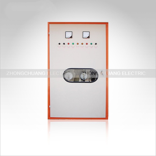
This series of thyristor rectifiers uses thyristor technology to convert AC power into adjustable DC power, primarily serving as a high-power adjustable DC power supply for metallurgical electrochemistry and electric heating. It can also be used as a current- and voltage-regulating adjustable DC power supply for general industrial resistive loads.
This equipment features a closed-loop control system with current and voltage negative feedback loops. Due to the adoption of a touchscreen digital control system, it boasts high voltage and current regulation accuracy. Users can select the current and voltage regulation operating state according to their production process. This equipment also offers excellent flexibility and intelligence, with comprehensive fault and alarm detection and protection functions (real-time detection of overcurrent, overvoltage, feedback loss, and internal control board faults; protection against start-up zeroing, soft start, current cutoff, voltage cutoff, emergency stop, phase loss, and water loss; in case of a fault, the AC side can trip and issue an audible and visual alarm, ensuring the reliability of equipment operation). It also features a user-friendly interface and excellent openness. Debugging is simple.
This equipment, using a thyristor as its working element, boasts advantages such as energy saving, vibration-free operation, noiselessness, small size, light weight, high rectification efficiency, wide voltage regulation range, and convenient operation and maintenance.
(2) Product Model Name
The model of this product is KHS-£££KA/£££V
£££KA—Rated DC Current
£££V—Rated DC Voltage
(3) This series of devices is suitable for the following working conditions:
l Altitude not exceeding 4000 meters.
l Ambient air temperature not higher than +40℃ and not lower than +5℃.
l Ambient air relative humidity not exceeding 85%.
l Ambient temperature change rate not exceeding 5K/h, relative temperature change rate not exceeding 5% per hour.
l Locations free from conductive dust, explosive gases, gases and vapors that corrode metals and damage insulation.
l Locations free from severe vibration and vertical tilt not exceeding 5℃.
l Thyristor devices are designed for indoor operation. Normal operating electrical conditions should meet the requirements of GB/T3859. The voltage waveform, fluctuation range, frequency variation, and symmetry of the AC power grid should comply with the relevant clauses of GB/T3859.1-93. The rectifier's suitability for electrical conditions should meet the Class B immunity requirements specified in GB/T3859.
2. Main Technical Data
Rated Input Voltage (Line Voltage): 110KV 35KV 10KV
Operating Mode: 100% continuous operation.
Cooling Method: Water cooling.
3. ZCH-12 Instructions for Use
(I) Communication, Networking, and Industrial Control Configuration
⑴ Communication Connection: A PC or PLC can communicate with one or more ZCH-12 six-pulse thyristor CNC controllers via a standard industrial RS485 communication port. The ZCH-12 thyristor CNC controller can only act as a slave device. Connect the standard industrial RS485 communication port of the PC or PLC to a twisted-pair shielded cable no longer than 1200 meters. Connect the other end of the twisted-pair cable to the S communication port of the ZCH-12 thyristor CNC controller.
⑵ Communication Protocol: ① Communication Protocol: Standard MODBUS-RTU protocol. ② Communication Interface: Lightning-resistant standard RS485 interface.
③ Baud Rate: 9600bit/s.
Functional Description:
◆ Small Dummy Load: Connect a piece of heating element to replace the real load, so that the DC current is 10-20A when the output rated DC voltage is applied.
◆ Intelligent Thermal Redundancy Control System: Two CNC controllers are interconnected with thermal redundancy ports, coordinating control in parallel, eliminating any control contention or exclusion. Seamless switching between master and slave controllers.
If the master controller fails, the redundant controller automatically and seamlessly switches to become the master controller, truly achieving dual-channel thermal redundancy control. This greatly improves the reliability of the control system.
◆ Seamless Switching Between Master and Redundancy: Two ZCH-12 control systems with hot redundancy allow for manual setting of which system acts as master and which as slave. The switching process is seamless.
◆ Redundancy Switching: If the master controller fails due to an internal fault, the redundant system automatically and seamlessly switches to master control.
◆ Pulse Adaptive Main Path: When a small dummy load is connected to the main path, and the voltage feedback amplitude is adjusted within the 5-8 volt range, the ZCH-12 automatically adjusts the pulse start point, end point, phase shift range, and pulse distribution sequence to adapt the pulse phase shift to the main path. No manual intervention is required, resulting in greater precision than manual tuning.
◆ Pulse Clock Selection: By selecting the pulse clock number, the pulse adapts to the main path phase for correct phase shifting.
◆ Pulse Phase Fine-Tuning: Through pulse phase fine-tuning, the pulse can be precisely aligned with the main path phase shift, with an error ≤1°. The fine-tuning value range is -15° to +15°.
◆ Two-Set Pulse Phase Adjustment: Changes the phase difference between the first and second sets of pulses. The adjustment value is zero. The phase difference between the first and second groups of pulses is 30°. The adjustment range is -15° to +15°.
◆ Channel 1F is designated as the first group of current feedback. Channel 2F is designated as the second group of current feedback.
◆ Automatic current sharing means that ZCH-12 automatically adjusts based on the deviation of the first and second groups of current feedback without manual intervention. Manual current sharing is achieved manually to achieve star and second group current sharing.
◆ Seamless switching: The power output remains unchanged during switching.
◆ Emergency stop function: When the FS terminal is shorted to the 0V terminal, ZCH-12 immediately stops sending trigger pulses. Sending trigger pulses is allowed when the FS terminal is left floating.
◆ Soft start function: When ZCH-12 is powered on, after self-test, the output slowly climbs to the given output. The standard soft start time is 5 seconds. Customizable time is adjustable.
◆ Zero return protection function: When ZCH-12 is powered on, after self-test, if the given value is not zero, no trigger pulse is output. Zeroing is enabled, and normal operation is achieved.
◆ ZCH-12 Software Reset: Resets the ZCH-12 by executing a software program command.
◆ ZCH-12 Hardware Reset: Resets the ZCH-12 via hardware.
◆ Phase Shift Range Selection: Range 0~3. 0: 120°, 1: 150°, 2: 180°, 3: 90°
◆ Permanent Parameter Saving: Control parameters changed during debugging are saved in RAM and will be lost during power outages. To permanently save the debugged control parameters: ① Set bits 1-8 of SW1 and SW2 to OFF, OFF, OFF, OFF, OFF, OFF, OFF, OFF, enabling saving;
② Enable the permanent parameter saving function; ③ Set all bits 1-8 of SW1 and SW2 to OFF, disabling saving.
◆ PID Parameter Self-Tuning: The controller automatically measures load characteristics to obtain the optimal algorithm for the load. More precise than manual adjustment. For special loads, the load characteristics are highly dependent on the load conditions and vary significantly; therefore, the PID controller must be manually tuned.
◆ PID Controller Selection:
PID0: Dynamic fast PID controller, suitable for resistive loads.
PID1: Medium-speed PID controller with excellent overall automatic adjustment performance, suitable for resistive-capacitive and resistive-inductive loads.
PID2: Suitable for controlled objects with high inertia, such as voltage regulation for capacitive loads and current regulation for inductive loads.
PID3-PID7: Manual PID controllers, allowing manual adjustment of P, I, and D parameter values. PID8-9: Custom-designed for special loads.


