Zinc smelting and purification involves two processes depending on the raw materials: zinc electrolysis and zinc electrowinning. The rectifier equipment is a key component in this process, significantly impacting the quality and energy cost of the zinc produced. A complete rectifier system includes a rectifier cabinet, digital control cabinet, rectifier transformer, pure water cooler, DC sensors, and DC switches. It is typically installed indoors near the electrolytic cell, using pure water cooling, and has input voltages of 35KV and 10KV.
I. Applications
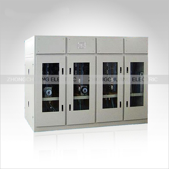
This series of rectifier cabinets is primarily used in various types of rectifier equipment and automated control systems for the electrolysis of non-ferrous metals such as aluminum, magnesium, manganese, zinc, copper, and lead, as well as chloride salts. It can also serve as a power supply for similar loads.
II. Main Cabinet Features
1. Electrical Connection Type: The connection type is generally selected based on the DC voltage, current, and grid harmonic tolerances. Two main categories are double-anti-star and three-phase bridge connections, with four different combinations available: six-pulse and twelve-pulse connections.
2. High-power thyristors are used to reduce the number of parallel components, simplifying the cabinet structure, reducing losses, and facilitating maintenance.
3. Components and fast-fusing copper busbars use specially designed circulating water circuit profiles for ample heat dissipation and improved component lifespan.
4. Component press-fitting adopts a typical design for balanced fixed force and double insulation.
5. Imported reinforced transparent soft plastic tubing is used for internal water connections, resistant to hot and cold temperatures and with a long service life.
6. Component radiator faucets undergo special treatment for corrosion resistance.
7. The cabinet is machined using fully CNC machine tools and features overall powder coating for an aesthetically pleasing appearance.
8. Cabinets are generally available in indoor open, semi-open, and outdoor fully sealed types, with inlet and outlet wiring designed according to user requirements.
9. This series of rectifier cabinets uses a digital industrial control trigger control system to enable the equipment to...
III. Technical Characteristics
1. Regulator: Digital regulators offer flexible and variable control modes and stable characteristics, while analog regulators provide rapid response. Both employ DC current negative feedback control, achieving a current stabilization accuracy better than ±0.5%. 2. Digital Trigger: Outputs 6-phase or 12-phase trigger pulses, with a double narrow pulse pattern spaced 60° apart. It features a strong trigger waveform, phase asymmetry ≤ ±0.3°, phase shift range 0~150°, and single-phase AC synchronization. High pulse symmetry is achieved.
3. Operation: Touch key operation enables start-up, shutdown, and current adjustment.
4. Protection: Includes no-current start, two-stage DC overcurrent alarm protection, feedback signal loss protection, water pressure and temperature over-limit protection, process interlock protection, and operating control angle over-limit indication. It can also automatically adjust the transformer tap position based on the control angle.
5. Display: LCD display shows DC current, DC voltage, water pressure, water temperature, oil temperature, and control angle.
6. Dual-channel product: During operation, the two channels serve as hot standby for each other, allowing for maintenance without shutdown and switching without (current) disturbance. 7. Network Communication: Supports multiple communication protocols including Modbus, Profibus, and Eathernet.
Voltage Specifications:
16V 36V 75V 100V 125V 160V 200V 315V 400V 500V 630V 800V 1000V 1200V 1400V
Current Specifications:
300A 750A 1000A 2000A 3150A 5000A 6300A 8000A 10000A 16000A 20000A 25000A 31500A 40000A 50000A
63000A 80000A 100000A 120000A 160000A
IV. Electrolytic Rectifier Technical Parameter Table
Main Specifications, Electrical Parameters, and Dimensions of Rectifier Units for Electrolysis
Introduction to Zinc Electrolysis Power Supply
Zinc electrolysis power supplies are generally low-voltage, high-current, constant-current adjustable DC power supplies.
Taking the matching rectifier cabinet: KGHS-18KA/165V as an example:
I. Main System Form: Double anti-star, same-phase, reverse-parallel thyristor rectification method. Each rectifier unit consists of one on-load tap-changing transformer and one 18KA thyristor rectifier cabinet, forming a 6-phase rectification. Two units can form a 12-pulse system.
II. Voltage Regulation Method: On-load autotransformer coarse adjustment, fine adjustment via thyristor phase-controlled voltage regulation; the rectifier unit is equipped with manual and automatic on-load switch range adjustment. Automatic adjustment is based on the control angle being controlled within the range of 5–25 degrees (to meet different usage conditions, users can set the on-load switch action value themselves on the host computer control system and touch screen).
III. Rectifier Parameters:
Rectifier Transformer Model: ZHPPS-4000/10
Voltage Regulation Range: 65%-105%
Pulse Count: 6 pulses per unit.
Number of Voltage Regulation Stages: 9-stage on-load tap changer regulation.
IV. Rectifier Cabinet Control and Protection:
4.1 Water circuit connections for rectifier element water coolers, rectifier bridge arms, and fast-acting fuse bridge arms employ scientific connection methods to minimize electro-corrosion. Stainless steel pipes are used, and all water nozzles are secured with stainless steel bolts to ensure leak-free operation under hot conditions. Flange connections are used where installation and disassembly are convenient.
4.2 Pure Water Cooling for the Main Rectifier Cabinet: The main cooling water manifold is made of stainless steel. Each cabinet has one inlet and one outlet water pipe. All water circuits are connected using rubber-reinforced pipes with mesh reinforcement. The water circuits must withstand a 30-minute test at 0.4 MPa water pressure without leakage, and the pipes must be easy and quick to disassemble.
4.3 Ensure rectifier components have sufficient contact pressure, rectifier arms have sufficient mechanical strength, economical current density, and good cooling effect.
4.4 Main circuit operation overvoltage protection. It is required to effectively absorb operational overvoltages and atmospheric overvoltages, and effectively absorb lightning strike overvoltages to ensure safe production operation.
4.5 Thyristor element commutation overvoltage protection. Install RC components with appropriate capacity parameters closest to the thyristor element, and keep the wiring as short as possible for thyristor commutation RC absorption protection.
4.6 Thyristor element fault protection. Use fast-acting fuses connected in series with the thyristor element for protection. When one fast-acting fuse blows, a fault indication of corresponding arm element damage is provided; when two fast-acting fuses blow, the pulse is blocked.
4.8 Overcurrent protection and overload alarm. When a short circuit occurs in the load or the current exceeds 105% of the rated value, an overcurrent protection signal will be sent to the PLC and an alarm will be triggered. When the load current exceeds 110% of the rated value, the system will issue an overload alarm signal and shut down. (Settings can be adjusted on the host computer control system).
4.9 Overheat Protection. Thermocouples monitor the circulating water temperature, and the collected analog signals are sent to the PLC. When the cooling water outlet temperature exceeds the set value, the PLC issues an overheat alarm signal. (Settings can be adjusted on the host computer control system).
4.10 Underpressure Protection. A pressure transmitter is installed on the stainless steel main inlet pipe, and the collected analog signals are sent to the PLC. When the inlet pressure is below 0.1MPa or the water supply is interrupted, the PLC issues an underpressure alarm signal. (Settings can be adjusted on the host computer control system).
4.11 Fuse Failure Alarm Monitoring System: The current operating status of all fast-acting fuses is reported to the PLC via communication through the fuse detection device. The overall alarm signal is also reported to the PLC via a pair of passive contacts. The operating status of all fast-acting fuses in the device is displayed on the touch screen and the host computer. In case of a fault, the location of the damaged fast-acting fuse can be quickly located. A green display indicates normal operation, while a red alarm indicates a fault, facilitating troubleshooting. 4.12 Feedback Off-Circuit Fault Protection. When the current feedback signal is open-circuited, the current stabilization control system automatically switches to open-loop operation and sends a feedback off-circuit fault signal to the PLC.
V. Computer Backend. The computer backend can monitor and adjust the rectifier voltage and current of the rectifier cabinet in real time. It can also monitor the operating status of each fast fuse, the operating temperature of each thyristor, the circulating water pressure and temperature, and the transformer oil temperature in real time. Protection parameters can be set and adjusted, and interfaces are available for electrolysis process parameters (voltage per cell, online pH monitoring, etc.) and electrolysis process linkage protection.